The W7RH Short Element Array Top Band Antenna System
For many years my
operation was limited in size and scope to a single transmitting and
receiving vertical. In the early years I used top-loaded verticals via
loading coil and small top-hat. In 1982 John Belrose(1) wrote an article
on top-loading via sloping wires. He refered to them as "Folded
Umbrella Top Loaded Antennas". I have built many in different sizes and
shapes to accommodate the space available. This design today remains my choice and I'm not surprised that W3LPL uses it in his low noise receiving array. The net result is a
short efficient 160m radiator with a feedpoint resistance of about 12
Ohms total. Ground loss is held to ~2 Ohms by installing more than 64
radials on each vertical. This is easily matched by a 4 to 1 un-un
transformer.
The W7RH 160m antenna is
simple but effective experiment in short top-loaded verticals. You might say this antenna system is unique as only three were ever built and this is the only one that remains in operation. The system is a hybrid driven and parasitic array. Measurements made during construction indicate the antenna currents are more than 90% of what is expected in their configuration. It is made up of 5 identical verticals, all 44 ft
in height and top loaded by two sloping 75 ft wires. All of the element
sloping top-hat loading wires are oriented in the same direction, in
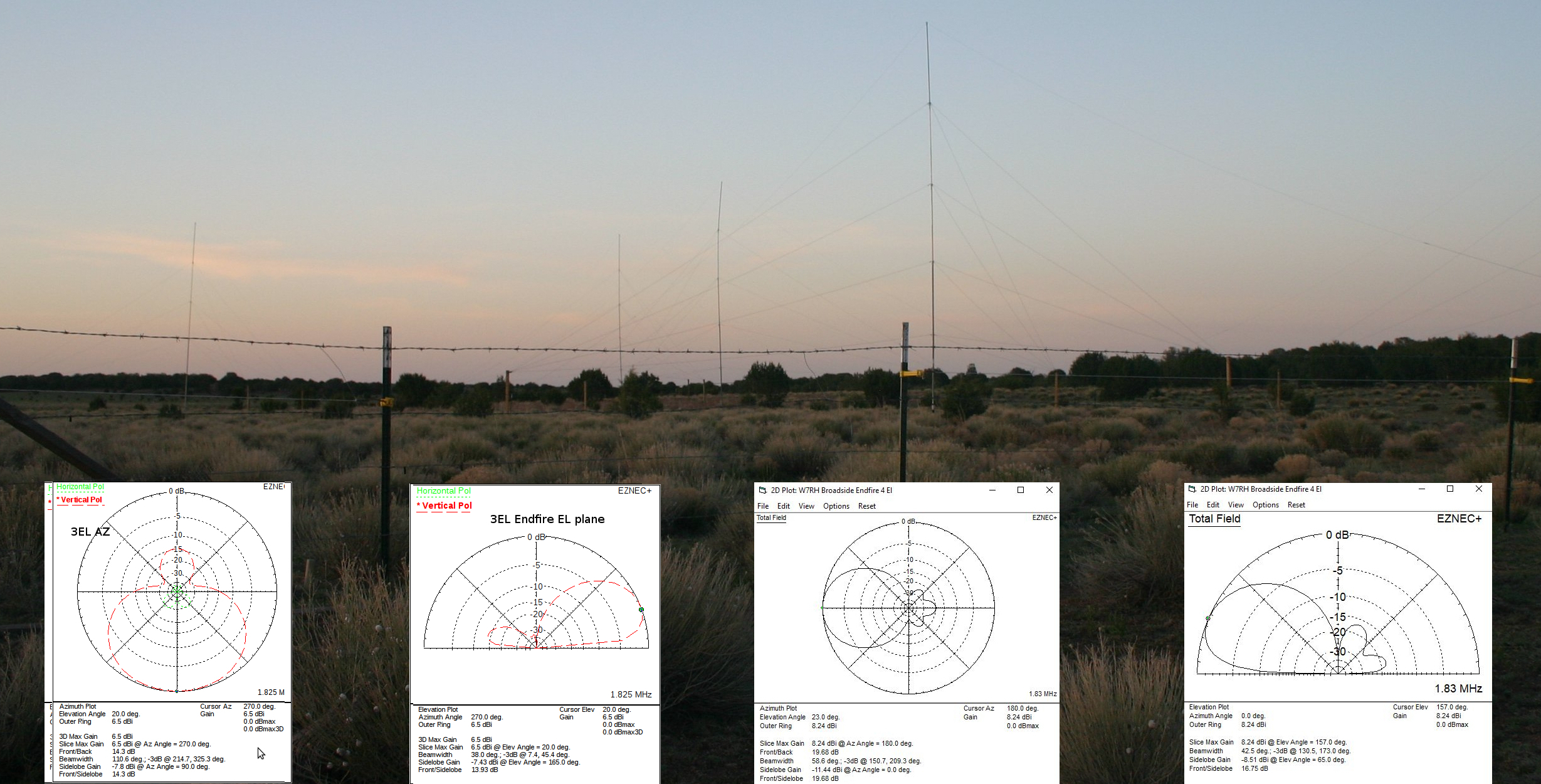
this case true North and South and end heights must be equal. (Note: Raising loading wire ends increases resonant frequency. Insure all loading wires are at same height for ease of tuning and maintenance.) Four of the verticals are aligned as a
broadside 4 element endfire colinear cell with two elements driven and two
elements as parasitic reflectors. The driven pair is spaced one half
wavelength and the distance between each reflector is one quarter wavelength.
These fire East and West with switching and yield approximately 7.83dBi
forward gain. The ultimate antenna pattern using parasitic elements is determined by element spacing. In this case design leaned towards maximum gain. This particular antenna configuration results in gain 1.4dBm less than a 8 Circle Array with the exception of East/West. It has ~2db more gain than a 4-Square. Because of geographic location the beam headings cover all primary population centers in the world. This was achieved with significantly less cost than the 8 Circle Array.
The center element allows
for OMNI, NE, SE, SW and NW coverage in three element endfire array
configuration.
The center element is driven and the opposite outside elements in-line
operate as either parasitic reflectors or directors. Each end fire array
yields about 6.5dBi gain.
Of special note, this
station is very remote and is completely off grid, with the nearest
commercial power about 10 miles away. The station consists of a Kenwood
TS-480 running 100W. In the winter, the solar arrays deliver about 4.8
kWh of power during a sunny day with 10 kWh storage. There is also a
supplemental 400W wind generator installed. This is enough power to run a
cold winter night of contesting using a computer, coffee pot,
micro-wave oven and lighting. I perform remote operation via a dedicated 4G
wireless link. The station is fully remote controlled including
remote turn on and full antenna switching. The site is monitored by
remote IP cams which email motion detected pictures of the grounds.
During all contests operation is local from the operating position which
occupies about 20 sq ft of space.
References:
(1) Belrose J.S VE2CV, "Folded Umbrella Top Loaded Vertical A", Ham Radio, September 1982, pp12-17
(2) My long time friends Jim Wilson, N7JW and Alan Van Buren, K7CA who
contributed tips on construction and alignment adapted from their
antenna arrays.(Right click mouse on image below for full image view.)
(1) Belrose J.S VE2CV, "Folded Umbrella Top Loaded Vertical A", Ham Radio, September 1982, pp12-17
(2) My long time friends Jim Wilson, N7JW and Alan Van Buren, K7CA who contributed tips on construction and alignment adapted from their antenna arrays.(Right click mouse on image below for full image view.)
Antenna Performance Specifications:
Area Required ~ 6 acres and corralled
Broadside Gain ~8.24dBi
Broadside Front to Back Ratio >15db
Endfire Gain ~6.5dBi
Endfire Front to Back Ratio >15db
Ground
system >100,000ft copper, Each element in the 4 element cell has 64
.3 wavelength radials, Center element has 120 .3 wavelength radials
Mast Height with insulator 44ft
2-1 swr bandwidth >60 kHz
Center Frequency 1830 kHz
Feedpoint Impedance 50 Ohms
Beam Headings 25, 90, 155, 205, 270 and 335 degrees true. Note: the antenna paterns represented are true for design CW frequencies. As you move up to the upper limit in frequency the F/B deteriorates by several dB but the gain remains fairly constant.
Broadside Gain ~8.24dBi
Broadside Front to Back Ratio >15db
Endfire Gain ~6.5dBi
Endfire Front to Back Ratio >15db
Ground system >100,000ft copper, Each element in the 4 element cell has 64 .3 wavelength radials, Center element has 120 .3 wavelength radials
Mast Height with insulator 44ft
2-1 swr bandwidth >60 kHz
Center Frequency 1830 kHz
Feedpoint Impedance 50 Ohms
Beam Headings 25, 90, 155, 205, 270 and 335 degrees true. Note: the antenna paterns represented are true for design CW frequencies. As you move up to the upper limit in frequency the F/B deteriorates by several dB but the gain remains fairly constant.