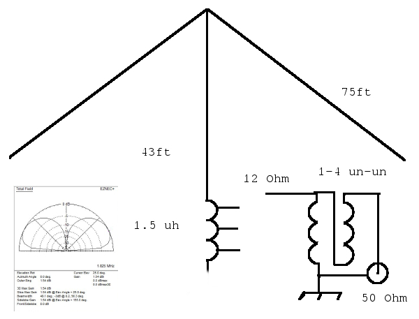
Without going into great detail, there are four relays providing switching for each element except for center driven element which uses just one relay to switch in and out. They are not shown in the drawing below as my intent is to show the key element, a simple efficient short vertical for the 160m band. Obviously they could be combined any way you want. Matching is provided by a un-un transformer with a 1-4 ratio. This provides a transformation of 50 Ohm feed line to the 12.5 Ohm antenna. This antenna is nearly equal in performance of a full sized vertical if and only if a full sized ground plane minimum of 60 .3 wavelength radials is installed.
With a 43ft mast and 75ft top loading wires the antenna is self resonant at 1.9 Mhz. The feed point impedance remains fairly constant up to about 70ft in height so the transformer can be used over that range. The top loading wires would have to be reduced in length accordingly. They extend outword from the mast at about a 70 degree angle. This results in the ends being about 20ft above the ground. The top loading wires must be equal length and equal height above the ground for the vertical pattern to be uniform.
The un-un transformer has a 4:1 ratio. In this application I used 6 bifilar wound turns on 1.5" ferrite toroid (permeability 250) using 16 gauge stranded teflon wire. This can handle up to 500W of power. The impedance transformation efficency is ~99%. (usual loss is about .1db) The ferrites are available from many sources. For higher power applications see "Understanding, Building, and Using Baluns and Ununs" by Jerry Sevick.
Note: When using multiple elements to form an array I use a relay to switch in a 2.5mh inductor from the bottom of the loading coil to ground. This will "detune" the antenna element to make it transparent when desired. Taps are used on the loading coil to select the desired operating frequency.